
AI-driven Submarine Design Optimization
Modern submarine design sits at a challenging intersection between performance, manufacturing, and operational constraints. The physics are well understood, the constraints are unforgiving, and the timelines keep compressing. Hydrodynamic performance matters enormously, along with other performance requirements such as acoustic stealth, detectability, structural integrity, and material limits under extreme pressure. Design decisions are also constrained by packaging, manufacturability, deployment logistics, survivability, and even a company’s visual brand. The result is a steady stream of geometry changes that all require validation, often through expensive and time-consuming CFD.
At the same time, Unmanned Underwater Vehicles (UUVs) are increasingly being developed as autonomous combat systems are deployed across land, air, and sea. Companies like Anduril, HII, General Dynamics, and Lockheed Martin are at the forefront of this development. Cost is a key competitive advantage, and few factors influence cost as directly as development timelines and engineering resourcing. CFD is used to evaluate the impact of design changes to the hydrodynamics of UUVs, and is often a major bottleneck.
This article walks through how Luminary built SHIFT-Submarine – a Physics AI model for submarine hydrodynamics that provides physics-based performance predictions in seconds. We’ll cover how it works, what the model actually learned, and why this approach has the potential to remove the simulation bottleneck that impacts UUV development timelines.
Enabling Design Teams
Figure 1: SHIFT-Submarine inference in Luminary’s interactive web app demo.
In many organizations, the limiting factor is not compute resources but access to expertise. One or two CFD specialists often become the central dependency for hydrodynamic insight across multiple programs. When they are overloaded or unavailable, iteration naturally slows or stops.
Physics AI changes this dynamic. Designers who are not CFD experts can explore hydrodynamic consequences directly, testing hypotheses and eliminating poor configurations without waiting in a queue. The goal is not to remove CFD engineers from the loop, but to reserve their time for simulations that require greater scrutiny and depth.
This becomes especially important when geometry changes are driven by non-hydrodynamic considerations. Deployment constraints, internal layout, and visual differentiation all introduce modifications that still need validation. Physics AI enables those checks to happen continuously rather than episodically.
Optimization with Physics AI
Figure 2: Optimization of a submarine design using SHIFT-Submarine inference.
From an analyst’s perspective, the true power of Physics AI is realized when the high-speed inference model is coupled with an optimization loop. By treating the Physics AI model as the performance evaluation engine, analysts can rapidly explore the vast multi-dimensional design space defined by the twenty-three geometric parameters. Instead of waiting days for a CFD solution to evaluate a single design, the optimization algorithm can query the AI model thousands of times in minutes. For example, a simple objective like minimizing the drag coefficient at a given velocity can be achieved with exceptional speed and efficiency. This framework allows design teams to quickly converge on an optimal geometry that respects the embedded engineering constraints, fundamentally changing the pace of early-stage design iteration.
To dive deeper into the technical aspects of coupling optimization algorithms with Physics AI, please register for our upcoming webinar.
Building SHIFT-Submarine
Luminary built SHIFT-Submarine in order to support these use cases.
The foundation of the model is a fully parameterized submarine geometry created in Onshape, spanning twenty-three geometric parameters across the forebody, mid-body, sail, strakes, and aft section. Rather than optimizing a single hull, the parameterization was designed to represent an entire family of vehicles, from compact unmanned underwater vehicles to larger manned platforms with fundamentally different cross-sections.
A key design decision was embedding engineering constraints directly into the CAD. As shapes vary, cross-sectional area is preserved to maintain internal packing volume for batteries, crew, and equipment. This reflects how real submarine design works. Length-to-diameter ratio, flat sections for internal volume, and sail placement are not free variables. They are negotiated compromises between hydrodynamics, transportation, ease of manufacturing, depth ratings (operating and crush depth), and feasibility.
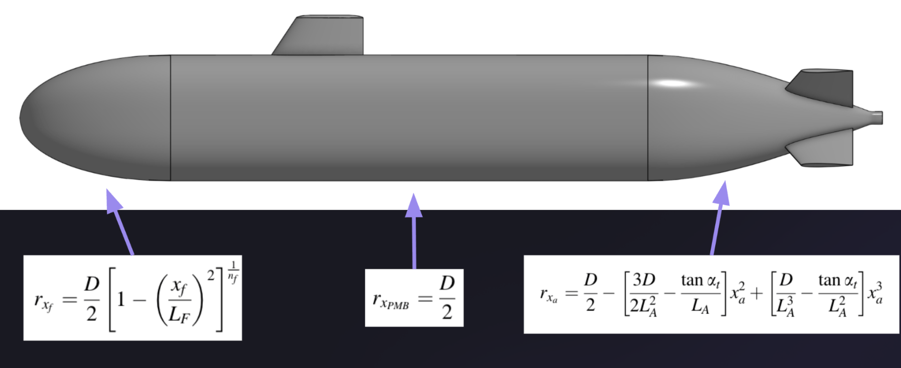
Figure 3: Hull geometry defined using lengthwise functions based on established submarine forms, with constrained volume preserved across shape changes.
The geometry itself is grounded in well-established submarine theory, including Myring-based hull definitions and symmetric NACA airfoil sections for sails and strakes, providing a robust physical baseline rather than an abstract optimization target.
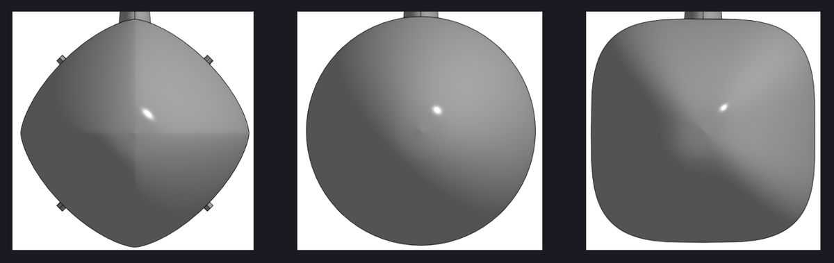
Figure 4: Cross-sectional variations across multiple vehicle families, with constant area maintained to preserve internal volume.
The model was intentionally trained to span multiple vehicle classes rather than a single configuration. This includes diamond-like cross-sections typical of smaller unmanned vehicles, more rectangular or squared sections for larger platforms, and intermediate nominal shapes. This matters because the economic value of physics AI compounds over time. A single upfront investment enables faster iteration across an entire product line and carries forward into future programs, rather than being tied to one vehicle.
Training Data from High-Fidelity CFD
Training data was generated using high-fidelity CFD across the parameterized design space. The initial quantity of interest was drag coefficient at zero angle of attack, reflecting early-stage hydrodynamic screening rather than maneuvering or control analysis.
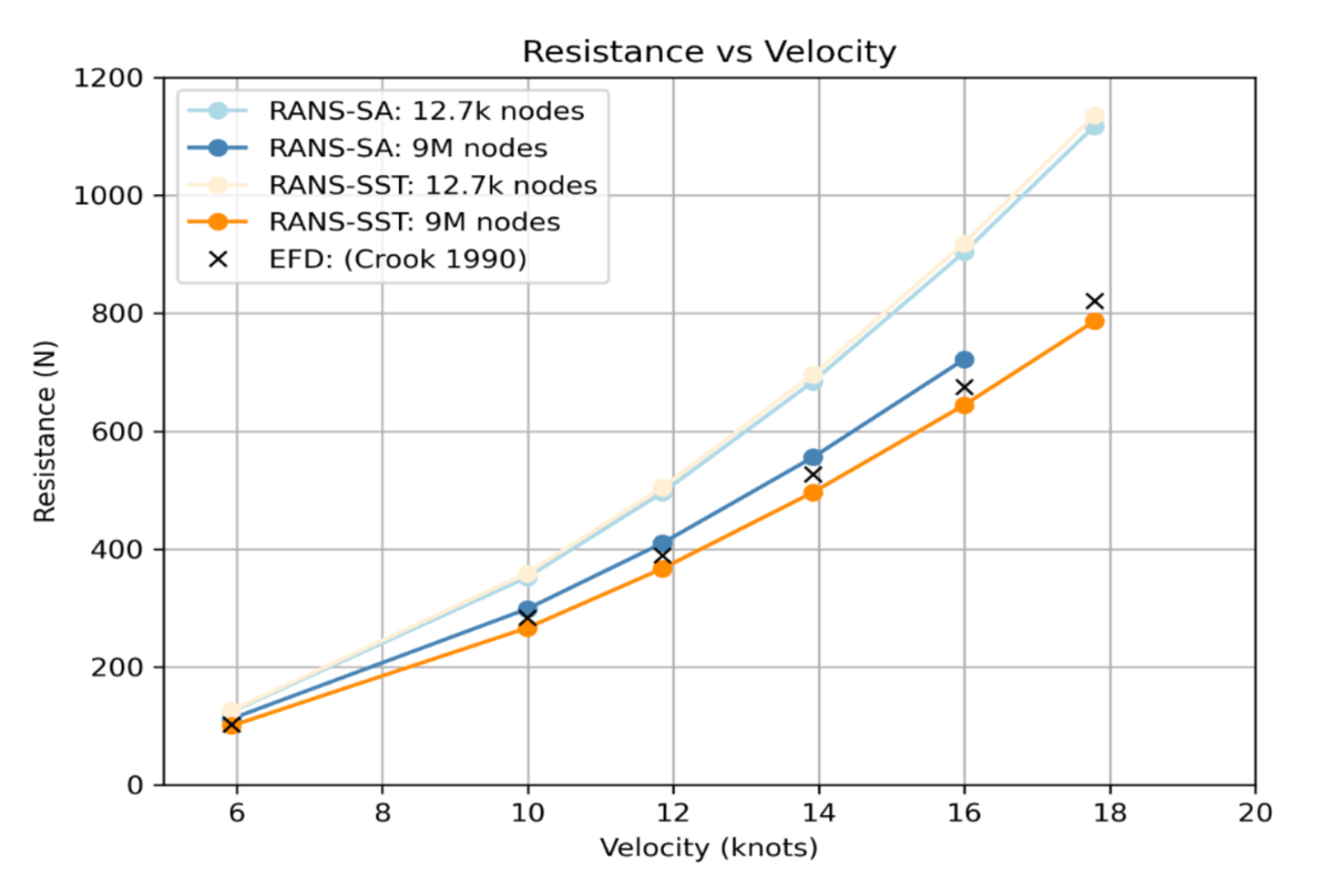
Figure 5: Resistance versus velocity and validation against experimental and reference data used to establish baseline CFD accuracy prior to model training.
The resulting model achieved sub-percent error on drag prediction, while reducing marginal evaluation cost to tens of dollars per design. Typically, a CFD analyst would be limited to analyzing a few hundred designs per year. This shift enables them to explore an order of magnitude more configurations within fixed program timelines.
What the Model Actually Learned
The strongest evidence that the model learned meaningful physics comes from its ability to accurately predict both wall shear stress and complex flow structures.
The model successfully captured the basic hydrodynamic features, such as the high-pressure region at the front stagnation point and the lower pressure near the hull’s aft taper. Furthermore, it excels at predicting one of the most significant, complex flow features in submarine hydrodynamics: the horse-shoe vortices off the sail and its interaction with the downstream wake off the aft section. This structure influences pressure distribution, drag, and the flow field entering the aft section of the vehicle which interacts with the propellers, impacting efficiency.
The inference model successfully captured this complex behavior. As sail position shifts, the model tracks corresponding changes in vortex location and wake structure. When the sail moves aft, the front edge of the wake moves aft as well. This reflects learned relationships between the design and wake development.
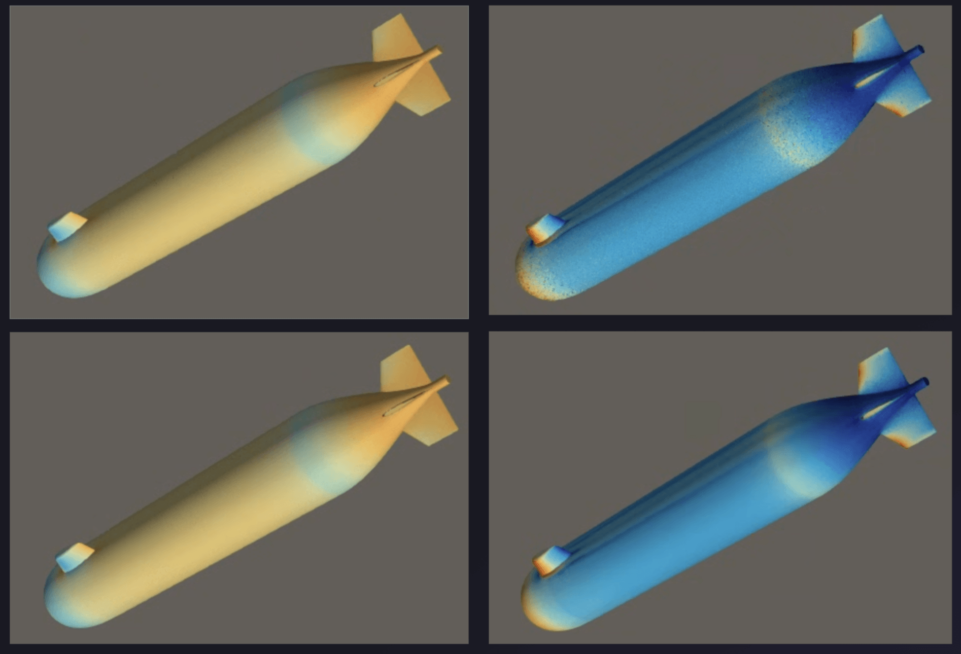
Figure 6: Iso-surface visualization showing sail-induced vortex structure and downstream wake, with geometry-dependent shifts accurately captured by inference.
The model also predicts the wakes behind the tail fins (sometimes referred to as the strakes). Smaller vortical structures behind the tail fins are also present and consistently predicted. The model also predicts the relatively high pressure loads and strain rates near the nose and tips of the strakes. While these features are subtle in water compared to high-speed aerodynamics, the pressure range is beyond an order of magnitude, making even the pressure distributions non-trivial. Furthermore, the main source of drag is viscosity (viscosity of water is significantly greater than viscosity of air), and the wall shear stress (WSS) range is also more than an order of magnitude, all of which matter for downstream integration and performance.
Flow Into the Propeller Plane
A particularly important downstream use case is propulsor integration. Propeller performance depends critically on the velocity and pressure field entering the propeller plane just aft of the tail fins. There is also the consideration of stealth: both the body and propeller can create disturbances in the water that can increase the signature of the vehicle.
While the inference model was not explicitly trained on propeller-plane metrics, the underlying CFD simulations demonstrate that the solver accurately predicts the flow field at this location. This creates a pathway for using physics AI models as a coordination layer between hull designers and propulsor teams, filtering candidate designs before expensive coupled analyses are required.
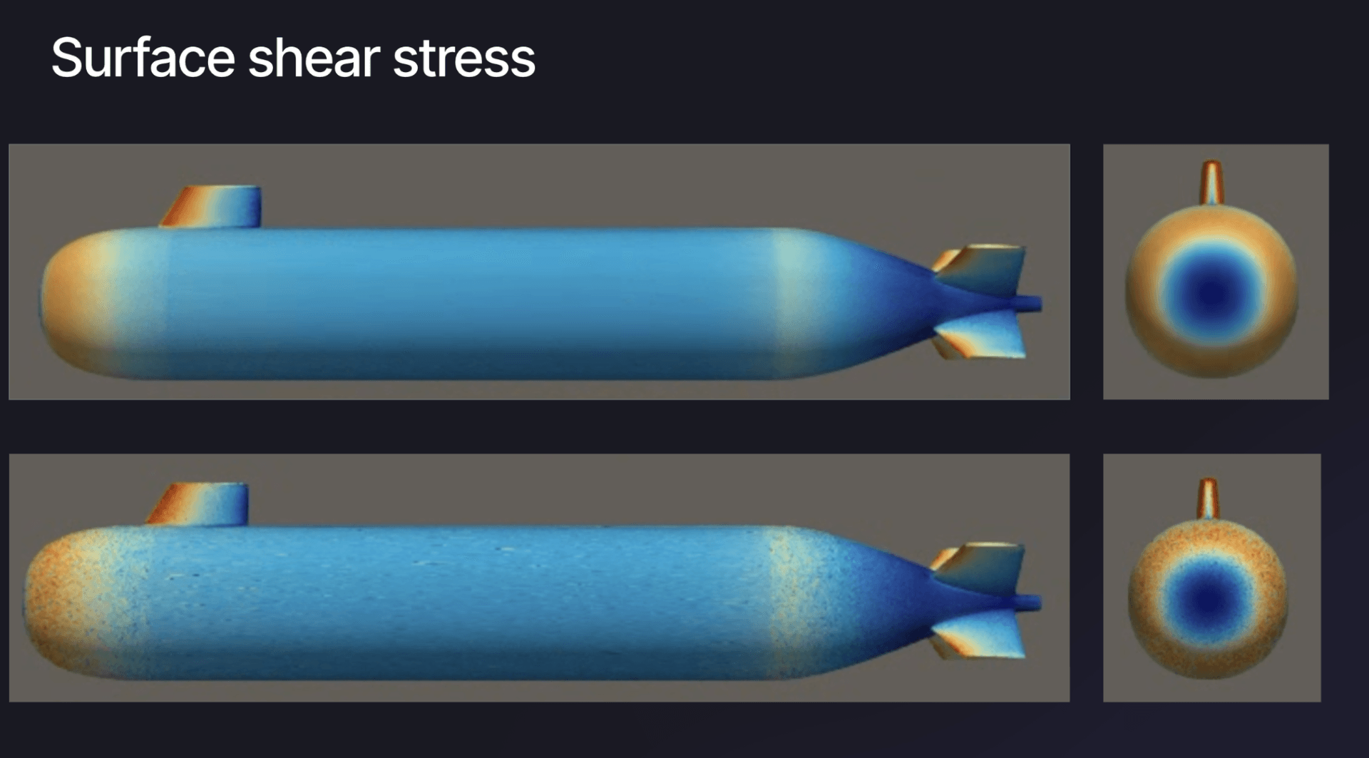
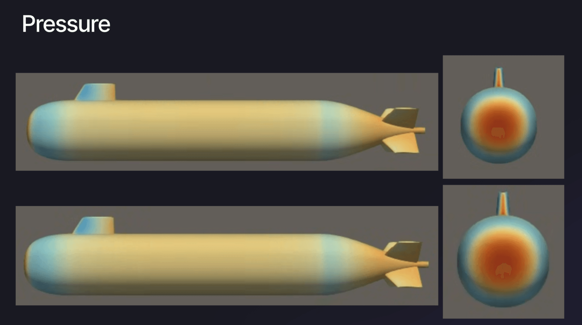
Figure 7: Pressure and surface shear stress distributions highlighting flow behavior approaching the propulsor mounting region.
What Comes Next
This initial model focuses on zero angle of attack and drag. That choice was deliberate. Lift and maneuvering signals are weak at zero angle and require different sampling strategies. Natural extensions include angle-of-attack sweeps, turning maneuvers, and explicit modeling of control surfaces.
These additions would extend the model’s applicability deeper into later-stage design decisions, where maneuverability, control authority, and mission-specific performance dominate.
Why This Matters
Engineering optimization is never about making something perfect. It is about making something good enough within real constraints. Physics AI is powerful precisely because it respects that reality. By learning from high-fidelity simulations that already encode engineering trade-offs, it gives teams faster access to credible answers without pretending those trade-offs do not exist.
For submarine and UUV design, that means more designs explored, fewer bottlenecks, smoother integration between teams, and better decisions made earlier, when they are cheapest to change.
Contact us if you’re interested in getting access to SHIFT-Submarine, or in building a Physics AI model for your use case. You can also try out an interactive demo of SHIFT-Submarine here.
