
2D Wall-Mounted Hump (Separated Flow)
validation
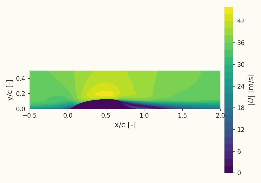
Overview
This case is the NASA wall-mounted hump (CFDVAL2004 Case 3), a benchmark for turbulence models in smooth-body separated flow. A turbulent boundary layer develops along a wind-tunnel floor and passes over a smooth Glauert-shaped hump. The adverse pressure gradient on the aft ramp drives the boundary layer to separate into a closed recirculation bubble that reattaches downstream. Because separation occurs off a smoothly curved surface (rather than at a fixed geometric edge), its location is set by the turbulence model. We run the no-flow-control baseline with the Spalart–Allmaras (SA) model.
The case is documented on the NASA Turbulence Modeling Resource, which publishes both reference CFD results (CFL3D) and the experimental measurements. We reproduce the surface pressure and skin-friction distributions and the separation/reattachment locations, comparing to CFL3D on the same grid and to the experiment.
Problem Setup
The hump has chord (normalized) and crest height . Flow conditions are and . The entire lower boundary is an adiabatic no-slip wall (the tunnel floor carrying the hump); the upper boundary is a contoured inviscid slip wall that approximates the end-plate blockage of the experiment; the upstream and downstream boundaries are characteristic (Riemann) far-field. The spanwise faces are symmetry planes (quasi-2D).
The discretization is density-based with a second-order FDS convective scheme; the SA freestream uses the standard . The computation reuses NASA's own published single-block structured grid family (103×28 → 817×217, each a 2× refinement), converted to the solver's quasi-2D mesh format. Reusing the identical CFL3D grids removes mesh resolution as a variable in the code-to-code comparison.
Quantities of Interest
The primary quantities are the surface pressure coefficient and the skin-friction coefficient along the tunnel floor, both normalized by the channel free-stream conditions, the static and dynamic pressure of the undisturbed core flow upstream of the hump, read from the converged solution, rather than by a nominal far-field value. This is the datum for a confined contoured tunnel, whose equilibrium free-stream static settles a few pascals off the imposed back pressure. On a curved wall the local surface tangent is inclined, so is taken as the wall-tangential component of the shear traction, matching the reference convention, not merely its streamwise-axis component. shows the suction peak over the crest and the pressure plateau over the separated region; gives the separation point (where first goes negative on the aft ramp) and the reattachment point (the downstream zero crossing). Both are compared to the NASA CFL3D reference (same grid, SA model) and to the CFDVAL2004 experiment. On the finest (817×217) grid, Luminary places separation at and reattachment at , versus CFL3D at 0.661 and 1.267 and the experiment at 0.746 and 1.116; both SA codes reattach downstream of the experiment.
Sources
Reference and from the NASA CFL3D code (817×217 grid, SA) and from the CFDVAL2004 experiment.
Source of the measured centerspan and .
Results
Surface pressure coefficient
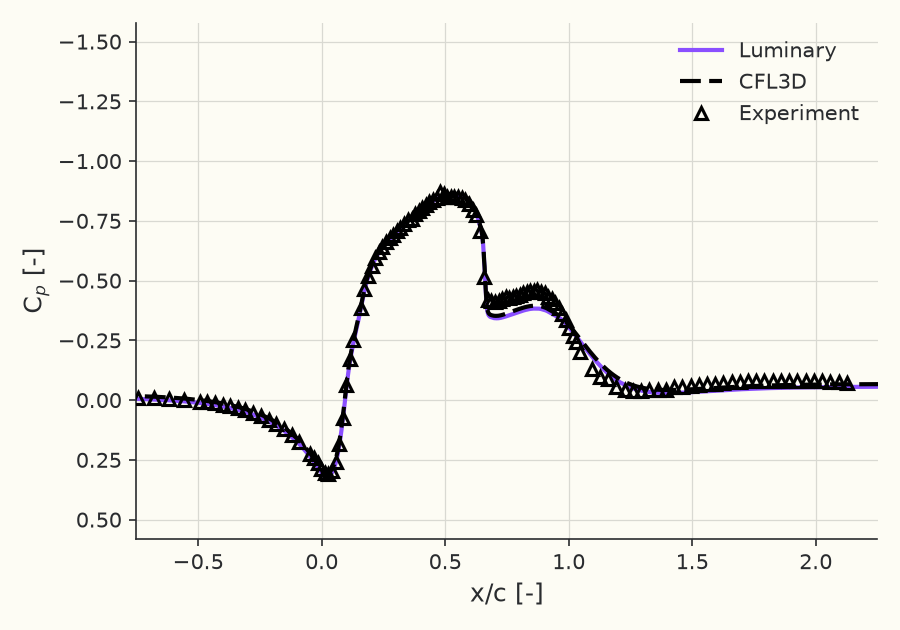
Reference: NASA Langley Turbulence Modeling Resource, "2D NASA Wall-Mounted Hump Separated Flow Validation Case" (SA model, no flow control). (CFL3D (817×217, SA), on the tunnel floor): https://tmbwg.github.io/turbmodels/nasahump_val_sa.html
Skin-friction coefficient
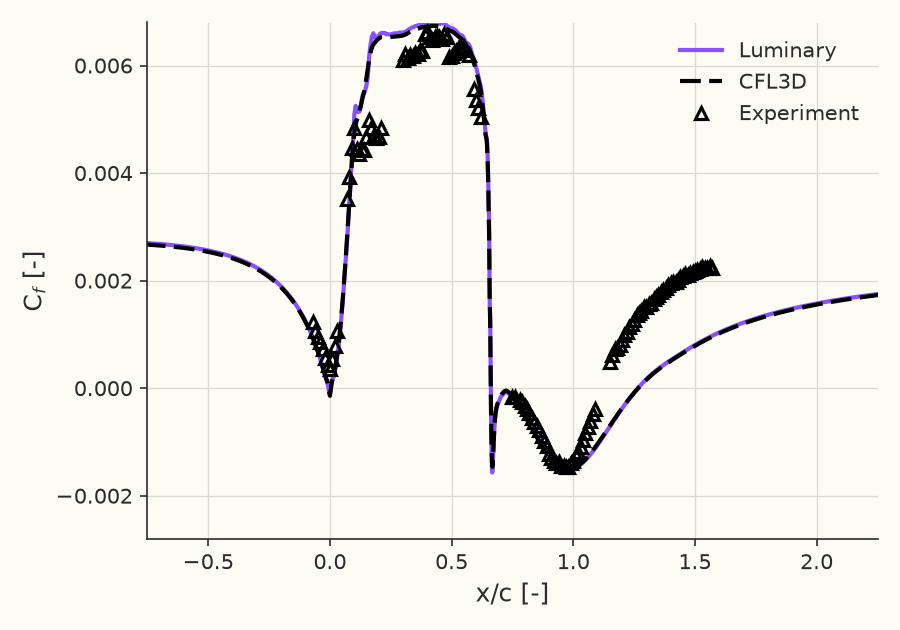
Reference: NASA Langley Turbulence Modeling Resource, "2D NASA Wall-Mounted Hump Separated Flow Validation Case" (SA model, no flow control). (CFL3D (817×217, SA), on the tunnel floor): https://tmbwg.github.io/turbmodels/nasahump_val_sa.html
Separation / reattachment vs CFL3D and experiment (finest grid)
| Code | ||
|---|---|---|
| Luminary | 0.661 | 1.265 |
| CFL3D | 0.661 | 1.267 |
| Experiment | 0.746 | 1.116 |
Values on the finest grid (817 × 217).
Separation and reattachment (the zero-crossings) on the finest grid against CFL3D (same grid, SA) and the experiment. Both SA codes reattach downstream of the experiment.
Grid convergence of the reattachment location
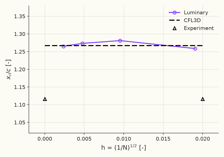
Reference: NASA Langley Turbulence Modeling Resource, "2D NASA Wall-Mounted Hump Separated Flow Validation Case" (SA model, no flow control). (CFL3D (817×217, SA), on the tunnel floor); D. Greenblatt et al., "A Separation Control CFD Validation Test Case," NASA CFDVAL2004 Workshop (Case 3); experimental data, NASA Langley. (CFDVAL2004 measured )
Solver configuration
- features exercised
- VerificationValidation2DRANSSpalart–AllmarasIdeal gasSteadyEnergy equation