
Supersonic Wedge (Oblique Shock)
verification
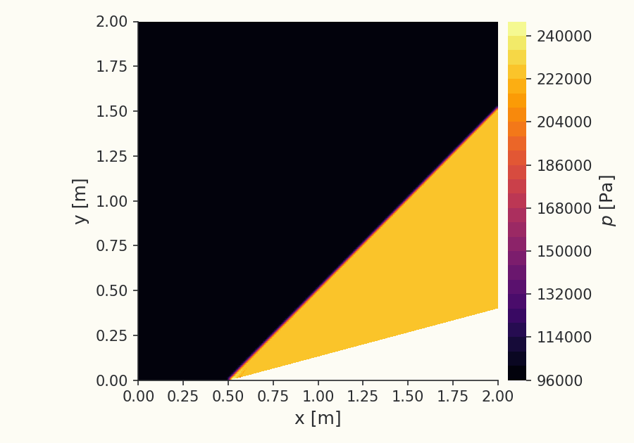
Overview
A supersonic stream that is forced to turn into itself by a concave corner compresses through an oblique shock, a planar discontinuity, attached to the corner, across which the flow deflects by the wedge angle while its pressure, density and temperature jump and its Mach number drops. For a given freestream Mach number and wedge half-angle the shock angle follows from the exact relation, and the post-shock state from the Rankine–Hugoniot jump conditions applied to the shock-normal Mach number. Below the detachment angle the relation has two roots; the smaller (weak-shock) root is the one realized on a slender wedge in a uniform stream.
Because the solution is closed-form and free of any empirical or turbulence modeling, it is used here to verify the solver's shock capturing and its compressible inviscid discretization: the shock should sit at the analytic angle and the captured post-shock state should match the analytic jump.
Problem Setup
A Mach-2 uniform stream enters a channel whose lower wall turns upward by at a corner; the upper wall is parallel and the domain is tall enough that the shock leaves through the downstream boundary rather than reflecting back into the measurement region. The flow is modeled as inviscid (Euler), compressible and steady, with an ideal gas (). Both walls are slip boundaries, the inlet imposes the supersonic freestream, and the outlet is a supersonic pressure outlet that extrapolates the interior state. A second-order FDS scheme with a Venkatakrishnan slope limiter is used, the limiter providing the monotone reconstruction at the discontinuity.
The grid is a structured compression-ramp mesh built so the ramp angle is exactly , with the resolution concentrated to capture a sharp, planar shock. For and the deflection is well below the detachment angle, so the shock is attached and the weak-shock branch applies.
Quantities of Interest
The verification quantities are the shock geometry and the post-shock state:
- the oblique-shock angle , fitted from the locus of the captured pressure jump;
- the static-pressure ratio across the shock;
- the post-shock Mach number ;
- the static-temperature ratio .
Each is compared to the exact and Rankine–Hugoniot result for , , .
Sources
Authoritative tabulation of the oblique-shock (θ–β–M) relation and the Rankine–Hugoniot normal-shock jump conditions used as the analytic reference.
Results
Oblique-shock angle and post-shock state vs the θ–β–M solution
| Source | [deg] | |||
|---|---|---|---|---|
| Luminary | 45.231 | 2.1951 | 1.4421 | 1.2713 |
| Analytic | 45.344 | 2.1947 | 1.4457 | 1.2694 |
Shock angle (fitted from the captured pressure jump) and the uniform post-shock , , .
Static pressure across the shock
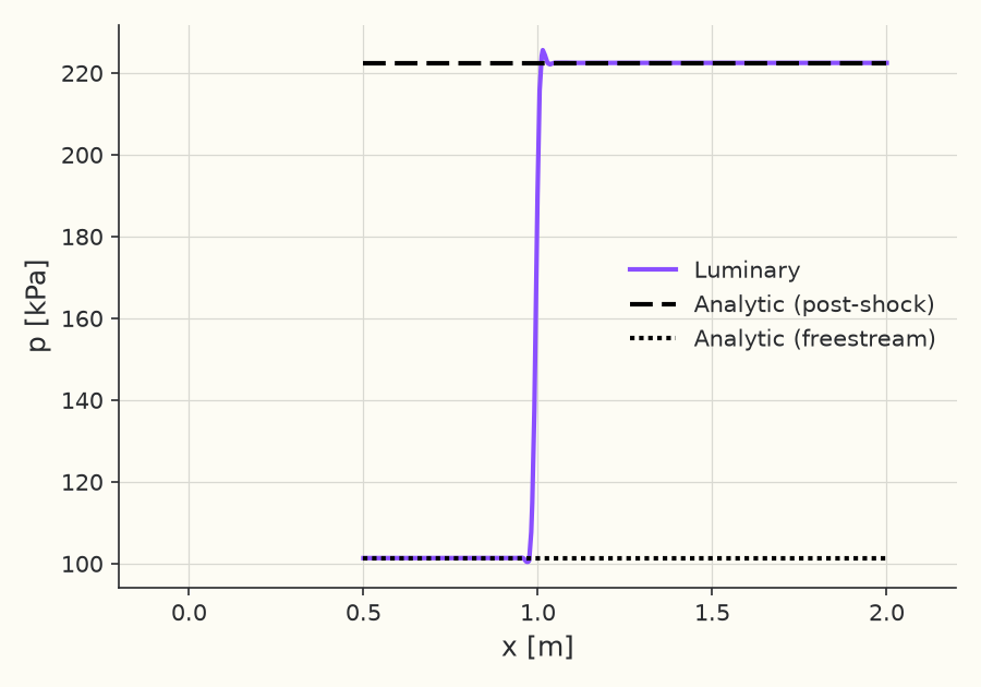
Reference: Ames Research Staff, "Equations, Tables, and Charts for Compressible Flow," NACA Report 1135, 1953. (θ–β–M relation and normal-shock relations for , , ): https://ntrs.nasa.gov/citations/19930091059
Solver configuration
- features exercised
- Verification2DInviscidIdeal gasSteadyEnergy equation