
Acoustic Point Source in a Uniform Flow: FW-H Against Direct CFD
verification
Animation of the divergence of the velocity (the dilatation) on a plane through the monopole source in a uniform flow at Mach (a) 0.25, (b) 0.5 and (c) 0.75, with the free stream in the direction. The flow convects the waves downstream.
Overview
A source at rest in a uniform flow radiates differently from the same source in still air: the flow convects the wave, so the tone is louder downstream than upstream and the contrast grows with the Mach number. This case places a monopole source in a uniform flow at Mach 0.25, 0.5 and 0.75, predicts the radiated tone with the Ffowcs Williams-Hawkings analogy evaluated on a permeable surface around the source, and compares its angular distribution with the pressure the flow solver computes directly at the same observer points.
Problem Setup
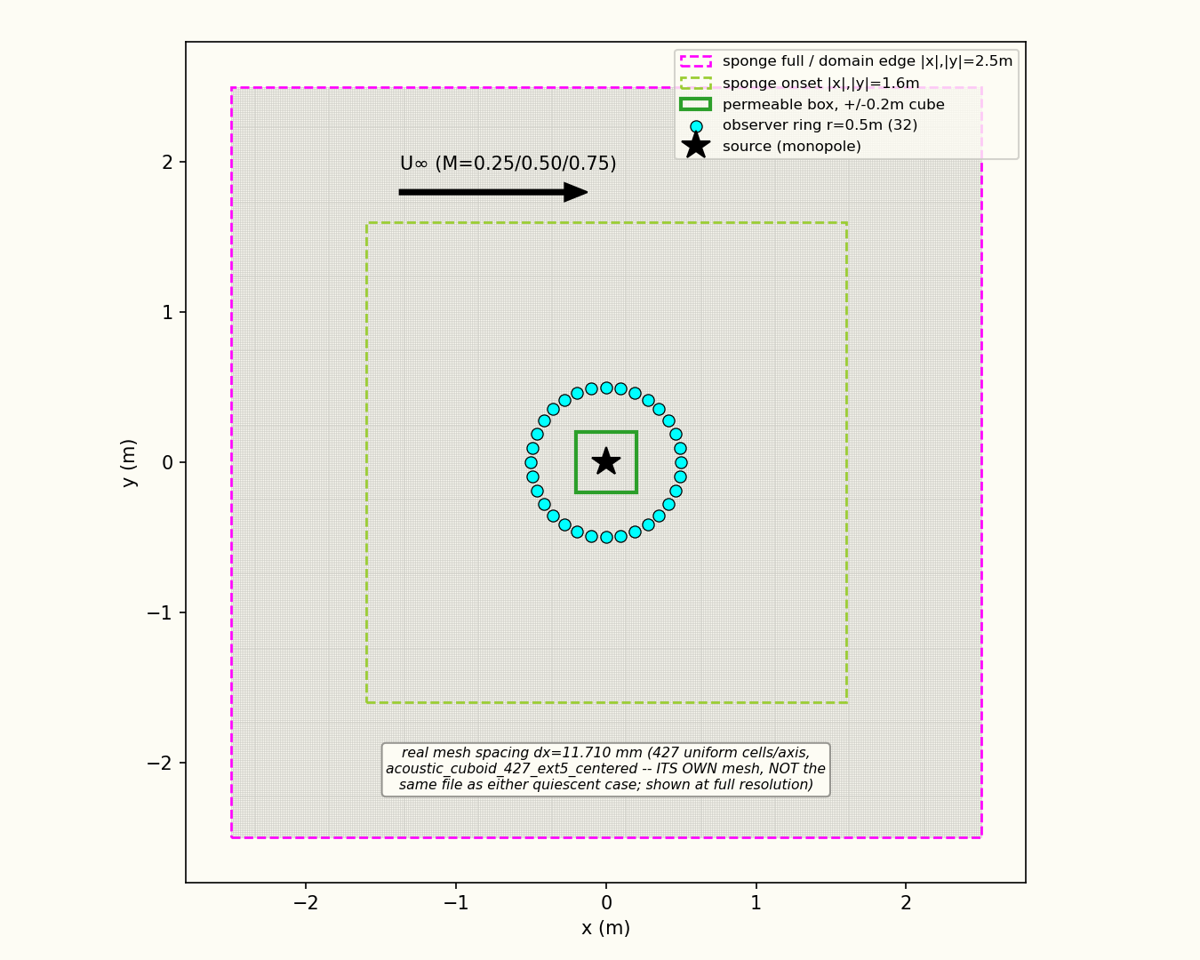
The domain is a three-dimensional box filled with a laminar ideal gas at Pa and K with a constant dynamic viscosity of kg/(m s), moving at the freestream Mach number. A sponge layer that absorbs the outgoing sound starts m from the source and is m thick. The source is a Gaussian isentropic mass source of width m, driven at Hz with a ramp over its first three periods. The Ffowcs Williams-Hawkings surface is a closed permeable box m on a side. The 32 observers are equally spaced on a ring of radius m about the source in the plane containing the flow. Time integration is second-order implicit with s, for 700 steps at Mach 0.25 and 0.5 and 1700 steps at Mach 0.75.
Quantities of Interest
The level of the source tone at each observer, from the Ffowcs Williams-Hawkings prediction and from the directly simulated pressure, over an observer-time window in which the tone is stationary.
Results
Mesh and domain
Tone level around the observer ring
Discussion
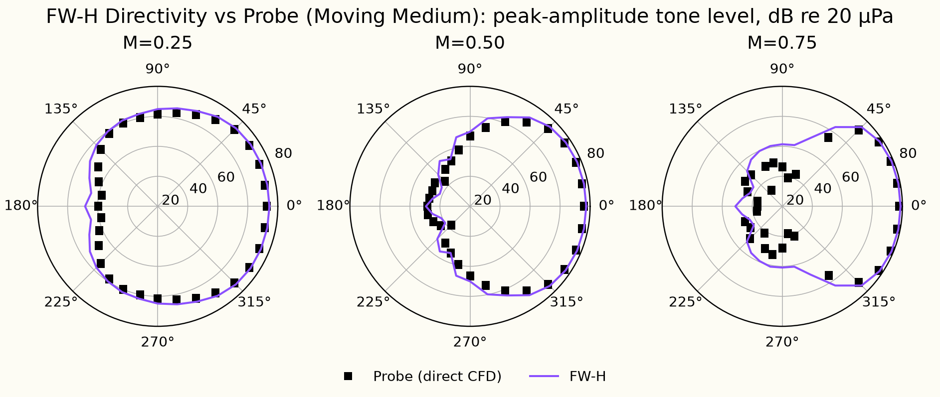
The tone-level plot shows how a uniform flow reshapes the sound of a source that, in still air, would be equally loud in every direction. The flow runs from left to right, so is directly downstream and directly upstream. At Mach 0.25 the pattern is still close to a circle, a little louder downstream. As the Mach number rises the tone gets louder downstream and quieter upstream; at Mach 0.75 the Ffowcs Williams-Hawkings (FW-H) level upstream is roughly 40 dB below the level downstream.
The FW-H method takes the flow solution on a box around the source and carries the sound from there to each observer with a formula that accounts for the uniform flow exactly, so nothing is lost on the way. The direct CFD (computational fluid dynamics) value is the wave after the solver itself has carried it across the grid to the observer, and every cell it passes through takes a little energy out of it. Because of this numerical dissipation, the directly computed level is expected to sit at or below the FW-H level, and a difference of a few decibels between the two is expected.
The flow makes this loss depend on direction. Waves travelling upstream are pushed back by the flow and squeezed together: at Mach 0.75 they are a quarter of their still-air length. The grid has about 11 cells per wavelength in still air ( mm against a wavelength of mm), so an upstream wave at Mach 0.75 is spread over fewer than 3 cells and is damped much more on its way to the observer. That is why, at Mach 0.75, the direct CFD points on the upstream side fall well inside the FW-H curve, while downstream, where the waves are stretched over more cells, the two lie on top of each other.
Solver configuration
- features exercised
- Verification3DLaminarIdeal gasUnsteadyEnergy equationFW-H (solid / permeable surface)