
NASA CRM-HL: High-Lift Prediction Workshop 5
Flagship benchmark showcase
Overview
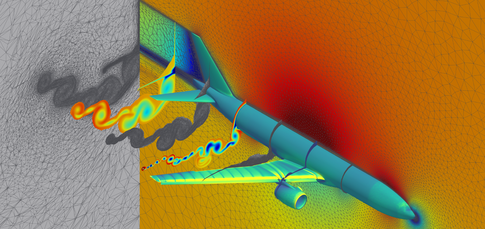
The AIAA CFD High-Lift Prediction Workshop series assesses the prediction of the flow around swept wings in landing and takeoff high-lift configurations, geometrically complex cases with slats, flaps, brackets and narrow gaps, often near and beyond the maximum-lift condition where large regions of separated flow appear. The fifth workshop (HLPW-5, 2024) used the high-lift Common Research Model (CRM-HL) and the Onera Large Reference Model.
This is a flagship benchmark: Luminary participated in the workshop and published the results reproduced here in an AIAA SciTech 2025 paper. The paper exercises Luminary's end-to-end GPU-native pipeline, geometry, meshing, RANS solver and solution-adaptive mesh refinement, on two classes of case: a verification study of the clean Wing-Body and a validation study of increasingly complex configurations. The figures and tables on this page are taken from that paper; they are not recomputed in this repository.
Problem Setup
All cases use ideal-gas air with Sutherland viscosity, no-slip adiabatic walls, and a far-field free-stream condition. Case 1 is the CRM-HL Wing-Body in free air at , and (reference static temperature 521 °R), run fully turbulent with two Spalart–Allmaras variants: the SA Standard model and SA-QCR2000-R (rotation correction with ). It is solved on the HeldenMesh 1.R.05 family (coarse/medium/fine = 2.63M / 17.8M / 131M cells), an additional 1.R.06 family extending to roughly two billion tetrahedra, and on Luminary-adapted (LMA) mesh series.
Case 2 is a configuration build-up: Case 2.1 adds empennage and flap fairings (CRM-HL WBHV), Case 2.2 adds slats and slat brackets, and Case 2.4 adds flaps and a nacelle. These are run with the SA Standard model over an angle-of-attack sweep that reaches and exceeds the maximum-lift condition, on meshes from 4.5M to 205M cells as well as LMA-adapted meshes targeting 100M cells. A lower angle-of-attack solution is used to warm-start the next higher incidence, as is done in wind-tunnel testing.
Quantities of Interest
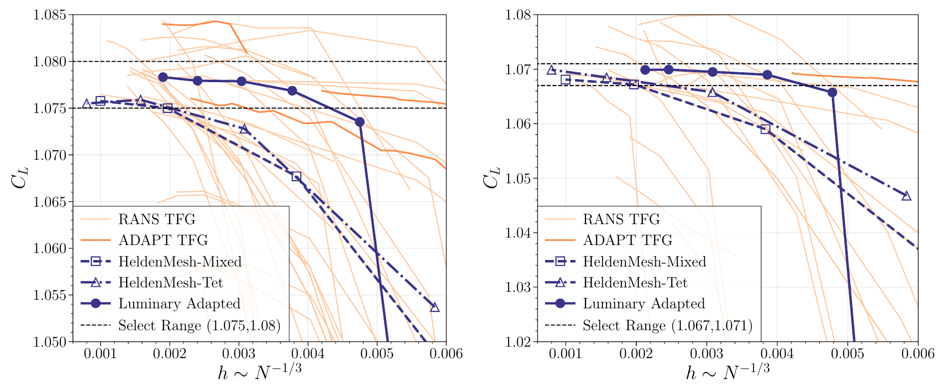
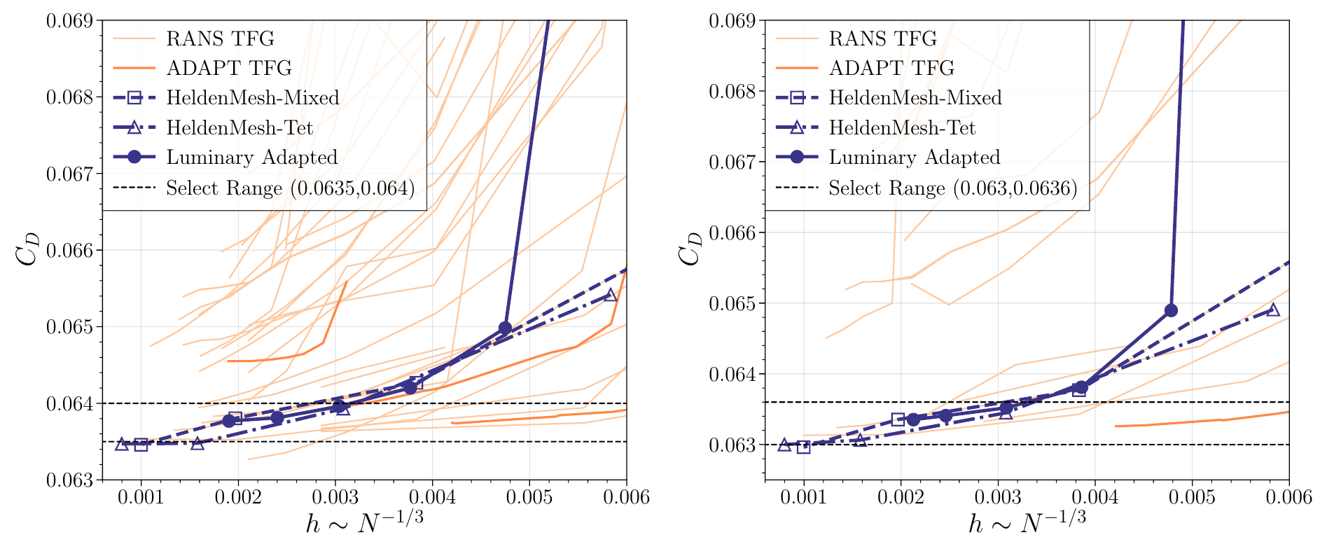
For Case 1 (verification) the quantities are the integrated lift, drag and pitching-moment coefficients , and , tracked under grid refinement against . The comparison is code-to-code: each Luminary series enters the workshop "select range" agreed by the participants as the grid is refined, for both turbulence models and on every mesh family. On the finest grids of the SA Standard study, HeldenMesh 1.R.05 (1.01B cells) gives , , ; HeldenMesh 1.R.06 (1.97B cells) gives , , ; and the Luminary-adapted series (145M cells) gives , , . The adapted series reaches the select range at roughly an order of magnitude fewer control volumes than the hand-built workshop grids.
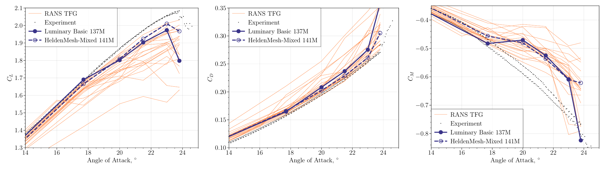
For Case 2 (validation) the quantities are the same force and moment coefficients as functions of angle of attack, compared against the wind-tunnel measurements. The validation probes the turbulence model and the meshing in the presence of geometry-driven flow separation, including the lift drop-off associated with slat-bracket wakes, through the maximum-lift condition. Case 2.2 is shown both on fixed meshes and with Luminary mesh adaptation (LMA), a solution-driven, metric-based anisotropic refinement that rebuilds the mesh from the flow field at each adaptation cycle. On the fixed meshes the lift dip near corresponds to the onset of slat-bracket-induced separation. The adapted result tracks the measured , and from through ; near an outboard slat-bracket wake separates and the lift curve shifts down to a parallel branch, consistent with the workshop's other adaptive submissions.
Sources
Luminary's HLPW-5 paper: solver/meshing/adaptation description and V&V results for Cases 1 and 2 (RANS and ADAPT Technology Focus Groups).
Workshop geometries (CRM-HL / Onera LRM), grid families and the wind-tunnel reference data for the configuration build-up cases.
Results
These results are reproduced from Luminary's published workshop submission (see Sources).
Case 1 grid convergence of
Reference: J. Krakos, J. Ho, P. Gomes, M. Mara, G. Sáez, A. Loseille, T. D. Economon and J. J. Alonso, "GPU-based and Adaptive Solution Technology for the 5th AIAA High Lift Prediction Workshop," AIAA SciTech 2025. (Case 1 grid convergence (workshop select range)): https://luminarycloud.com
Case 1 grid convergence of
Reference: J. Krakos, J. Ho, P. Gomes, M. Mara, G. Sáez, A. Loseille, T. D. Economon and J. J. Alonso, "GPU-based and Adaptive Solution Technology for the 5th AIAA High Lift Prediction Workshop," AIAA SciTech 2025. (Case 1 grid convergence (workshop select range)): https://luminarycloud.com
Case 1 finest-grid force coefficients (SA Standard)
| Mesh series | [cells] | |||
|---|---|---|---|---|
| HeldenMesh 1.R.05 | 1.01B | 1.07577 | 0.063459 | -0.065553 |
| HeldenMesh 1.R.06 | 1.97B | 1.0755 | 0.06347 | -0.065486 |
| Luminary Adaptive | 145M | 1.07832 | 0.063768 | -0.066366 |
Values on the finest grid (finest grid in each family).
Finest-grid , and for the CRM-HL Wing-Body (Case 1, SA Standard) on each mesh family. The two HeldenMesh grids reach nearly two billion cells; the Luminary-adapted series reports comparable coefficients at 145 million cells: roughly an order of magnitude fewer control volumes.
Reference: J. Krakos, J. Ho, P. Gomes, M. Mara, G. Sáez, A. Loseille, T. D. Economon and J. J. Alonso, "GPU-based and Adaptive Solution Technology for the 5th AIAA High Lift Prediction Workshop," AIAA SciTech 2025. (Case 1 grid convergence (workshop select range)): https://luminarycloud.com
Case 2.2 force and moment versus angle of attack (fixed meshes)
Reference: J. Krakos, J. Ho, P. Gomes, M. Mara, G. Sáez, A. Loseille, T. D. Economon and J. J. Alonso, "GPU-based and Adaptive Solution Technology for the 5th AIAA High Lift Prediction Workshop," AIAA SciTech 2025. (Case 2.2 force/moment vs angle of attack (fixed meshes)): https://luminarycloud.com
Case 2.2 force and moment versus angle of attack (adapted meshes)
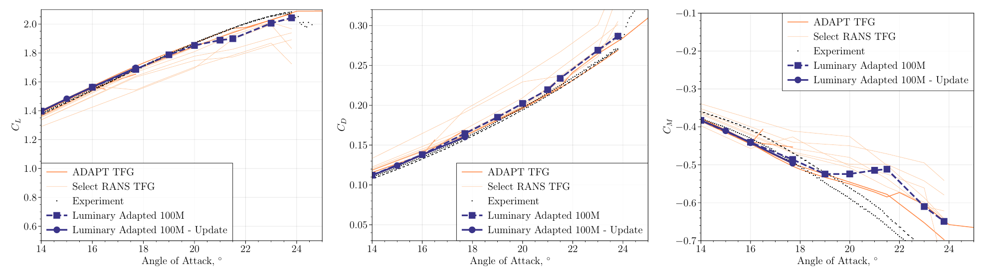
Reference: J. Krakos, J. Ho, P. Gomes, M. Mara, G. Sáez, A. Loseille, T. D. Economon and J. J. Alonso, "GPU-based and Adaptive Solution Technology for the 5th AIAA High Lift Prediction Workshop," AIAA SciTech 2025. (Case 2.2 force/moment vs angle of attack (adapted meshes)): https://luminarycloud.com
Solver configuration
- features exercised
- VerificationValidation3DRANSSpalart–AllmarasIdeal gasSteadyEnergy equation