
Aeolian Tone of a Circular Cylinder: FW-H Against Direct CFD
verification
Animation of the divergence of the velocity (the dilatation) on a plane through the cylinder, which shows the sound radiated by the vortex shedding, with isosurfaces of the vortical structures in the wake.
Overview
A cylinder in a cross-flow sheds vortices alternately from its two sides; the resulting lift fluctuation radiates a tone, the Aeolian tone, whose frequency is set by the flow and whose angular pattern is that of a dipole aligned with the lift direction. This case computes the flow with an unsteady Reynolds-averaged simulation, predicts the radiated tone with the Ffowcs Williams-Hawkings analogy evaluated both on the cylinder wall and on a closed permeable surface in the same solution, and compares it with the pressure the flow solver computes directly at the same observer points.
Problem Setup
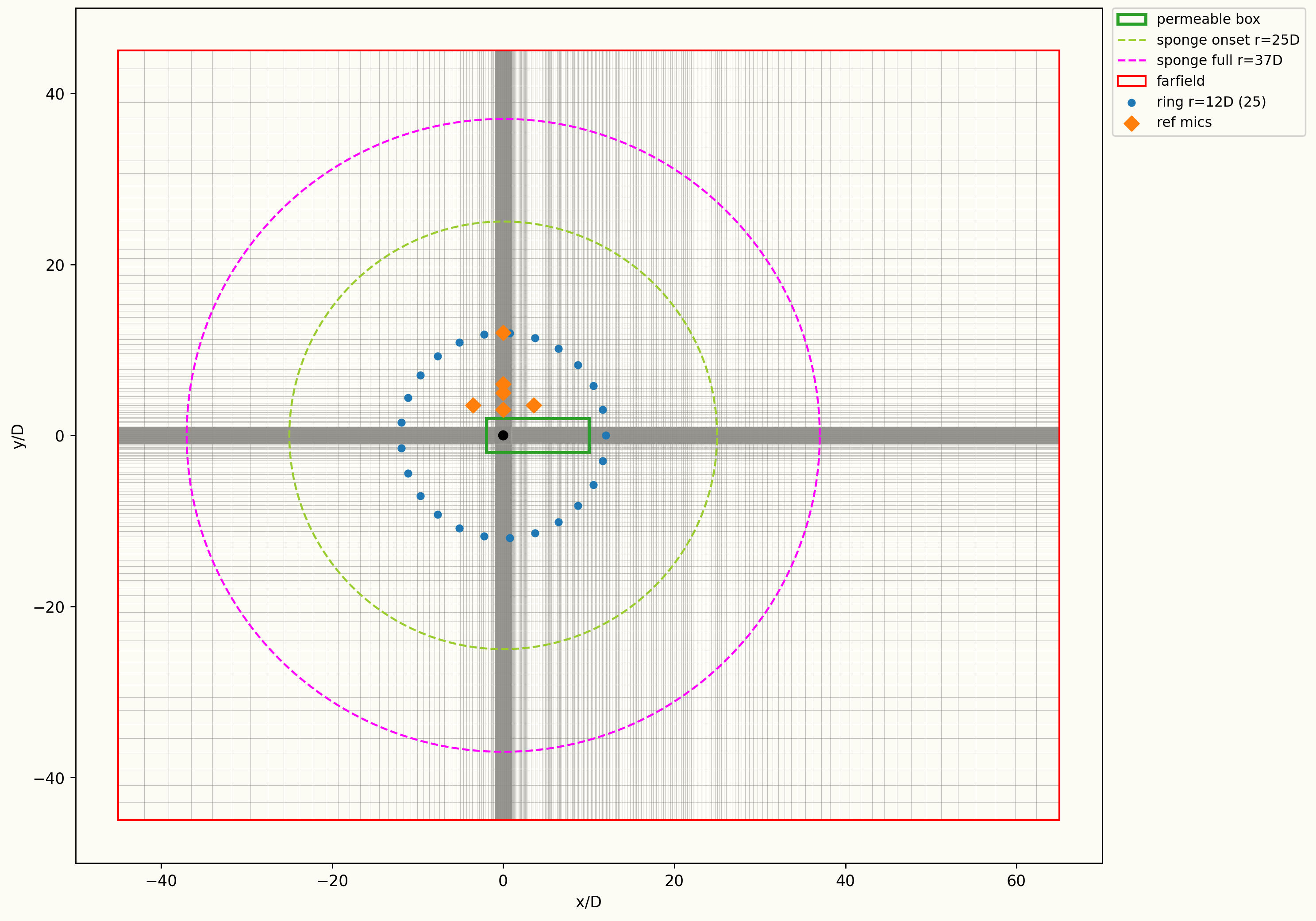
The flow is at ( m/s, K, Pa) over a cylinder of diameter . The domain is periodic in the spanwise direction over , and a sponge layer that absorbs the outgoing sound starts at and is thick. The flow is computed with an unsteady Reynolds-averaged simulation using the Spalart-Allmaras turbulence model, the fluid is an ideal gas with Sutherland viscosity, and time integration is second-order implicit with s. The permeable surface is a box spanning and over the full span, and both Ffowcs Williams-Hawkings integrals are repeated over 25 copies of the span to represent a long cylinder. There are 48 observers at mid-span: six microphones between and from the cylinder, and a ring of radius with extra observers around the two quiet directions along the flow axis.
Quantities of Interest
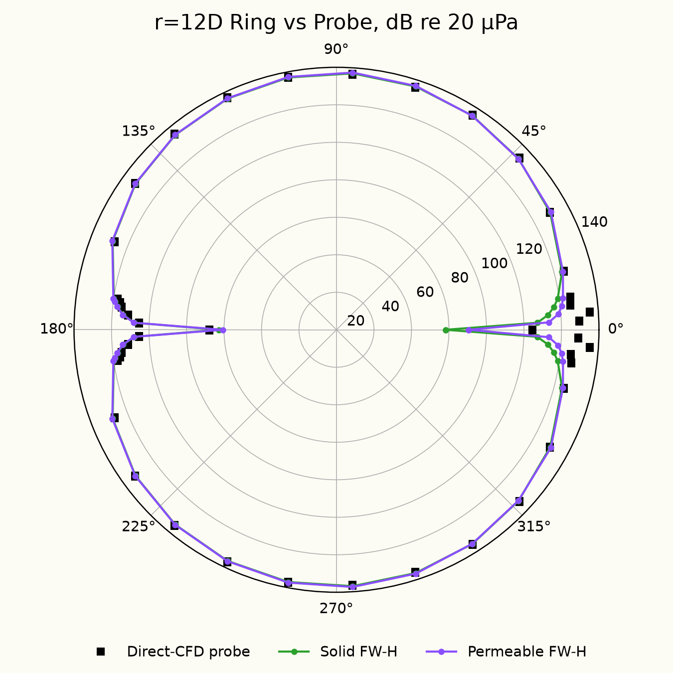
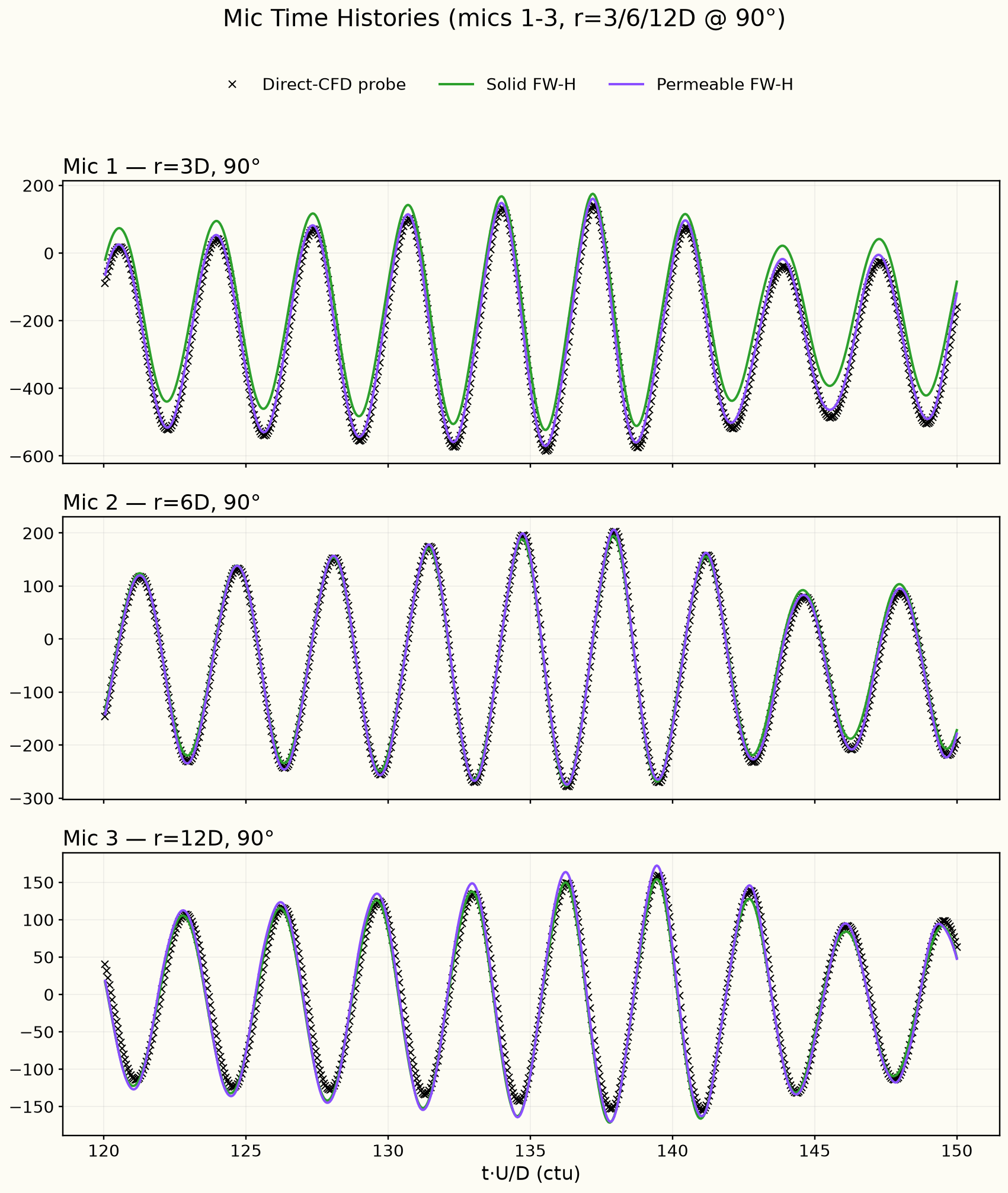
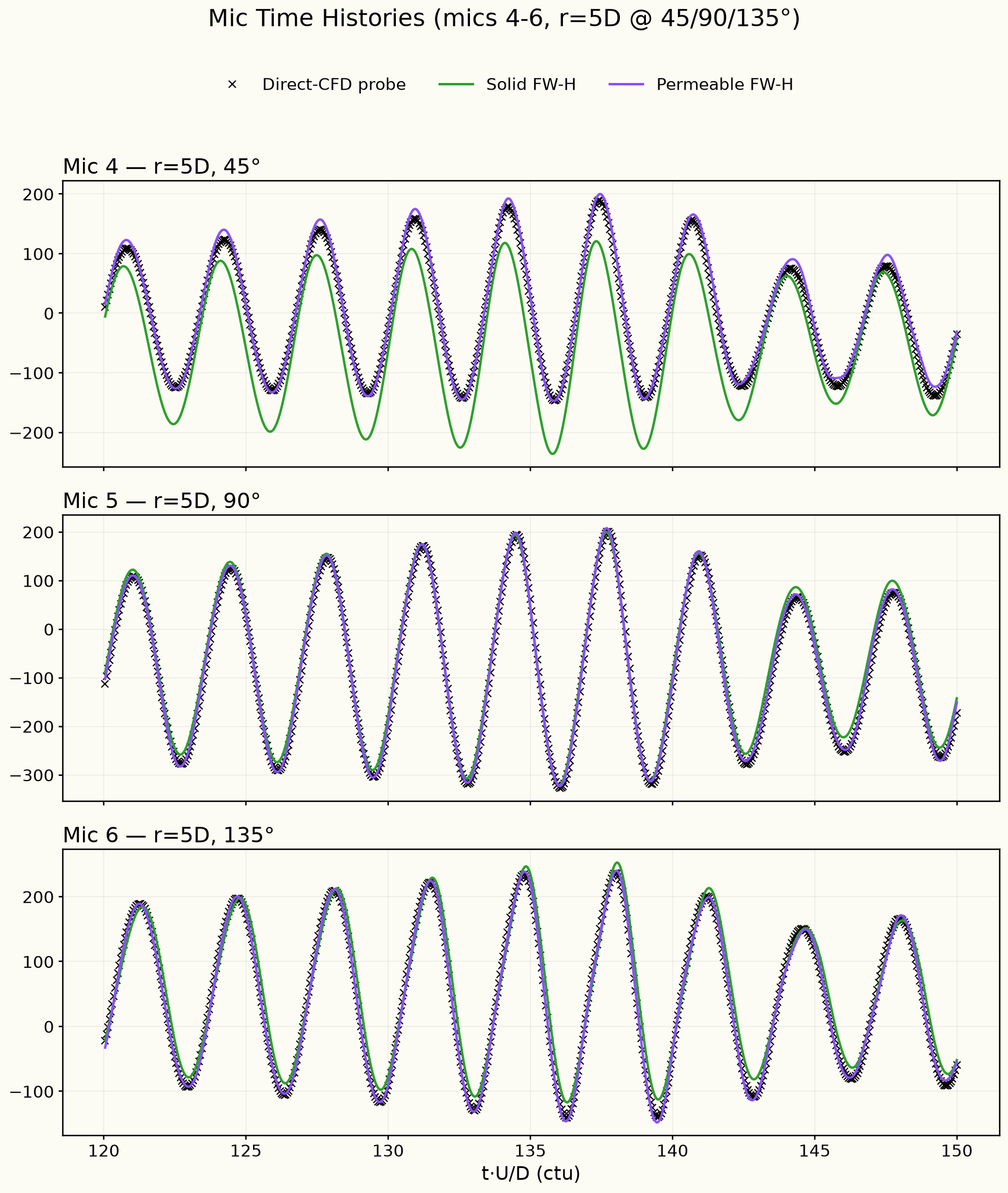
The level of the shedding tone at the ring observers, from both Ffowcs Williams-Hawkings surfaces and from the directly simulated pressure, over the window , and the pressure time histories at the six near-field microphones, from the three sources.
Results
Mesh and domain
Tone level on the observer ring
Microphone pressure at , and
Microphone pressure at , and
Discussion
The Aeolian tone is the hum a wire or a pole makes in the wind. Vortices shed alternately from the two sides of the cylinder push it up and down, so it radiates like a dipole: loud above and below the cylinder, quiet along the flow direction. The plot of the tone level on the ring shows this pattern, and the Ffowcs Williams-Hawkings (FW-H) predictions from the cylinder wall and from the permeable surface lie on top of the pressure the solver samples at the same points.
Some difference between FW-H and direct CFD (computational fluid dynamics) is expected. The FW-H method takes the flow solution on a surface close to the cylinder and carries the sound from there to each observer with a formula that is exact for sound travelling through a uniform flow, so nothing is lost on the way. The direct CFD value is the wave after the solver itself has carried it across the grid, and every cell it passes through takes a little energy out of it. Because of this numerical dissipation, the directly computed level tends to sit at or slightly below the FW-H level, and the gap grows with distance.
Directly downstream, near , the ring observers sit in the wake. There the pressure the solver samples includes the passing vortices themselves and not only sound, and the direct CFD points lie above the FW-H curves.
The two microphone plots compare the pressure signals themselves over the analysis window, not just their levels. The tone rises and falls in strength over the window, and both FW-H predictions follow the solver's pressure through it, in shape and timing, at all six microphones. The permeable-surface prediction also matches its level at every microphone. The cylinder-wall prediction is shifted slightly at the two microphones closest to the shed vortices: above the cylinder, and away at on the downstream side. This is expected. The cylinder-wall surface counts only the sources on the cylinder itself, while close to the cylinder and its wake the pressure the solver samples also includes the pressure of the vortices shed into the flow. The permeable surface encloses the cylinder and the near wake, so it accounts for them. Further out, or upstream, the pressure of the vortices has fallen off, since it decays with distance faster than sound does, and the two surfaces agree.
Solver configuration
- features exercised
- Verification2DRANSSpalart–AllmarasIdeal gasUnsteadyEnergy equationFW-H (solid / permeable surface)