
2D Asymmetric Plane Diffuser (SST)
validation
Overview
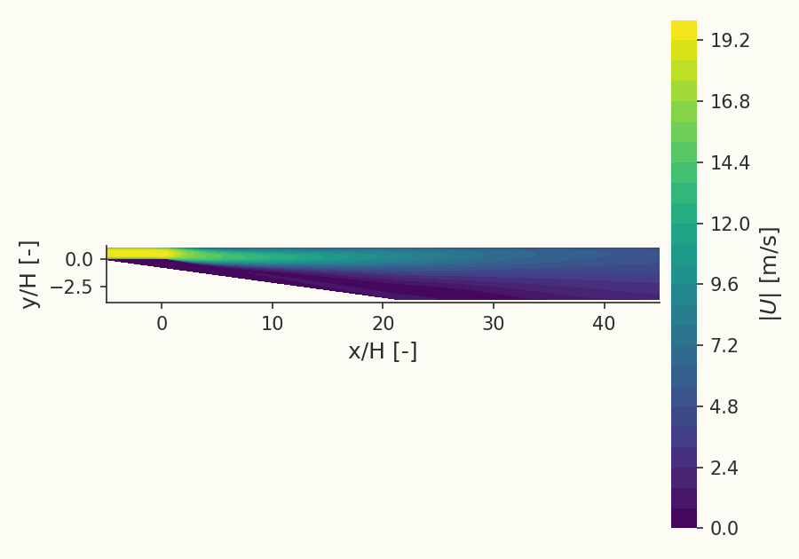
This case validates the solver's prediction of turbulent boundary-layer separation under an adverse pressure gradient in the asymmetric plane diffuser of Buice & Eaton, run with the k-omega SST turbulence model and compared to the WIND SST computation of NASA/TM-2005-213894. A fully developed plane-channel flow enters a one-sided diffuser: the lower wall is inclined at while the upper wall stays flat, so the cross-section opens to 4.7 times the inlet height. The resulting deceleration sets up an adverse pressure gradient that separates the boundary layer on the inclined wall, producing a recirculation bubble that reattaches downstream while the flat wall stays attached. Because the separation occurs on a smooth (geometrically un-forced) wall, its location and extent depend on the turbulence model's response to the pressure gradient, which makes the configuration a test of RANS closures. The skin-friction quantities the reference paper reports for its SST run are reproduced here: skin friction on the upper (flat) wall and skin friction on the lower (inclined) wall, with the Buice & Eaton measured skin friction overlaid for comparison.
Problem Setup
The geometry follows the reference paper, with the inlet channel height as the reference length. A straight inlet channel long upstream of the diffuser lets the wall boundary layers develop naturally, so no profile-inlet boundary condition is needed. The inclined wall descends at over a length of to an exit height of , rounded with fillets at the start and end of the ramp (matching the experiment's contoured corners); the start of the expansion is . A recovery channel extends downstream so the separated shear layer reattaches and the boundary layer redevelops. The Reynolds number is , based on the inlet centerline velocity and , with the viscosity held constant to fix it. Turbulence is modelled with k-omega SST, integrated to the wall.
The mesh is the paper's recommended baseline grid at a near-wall spacing of . The paper's own grid-resolution study (coarse , medium , fine , all at ) found the medium and fine grids essentially identical and selected the medium grid for all SST runs; the first off-wall cell here sits at . Because the comparison is against a single published SST curve set on this grid-independent mesh, a single converged grid is reported rather than a grid-convergence sweep.
The boundary conditions replicate the WIND deck by type, not merely by flow state: a compressible ideal-gas flow at Mach (static psia, ; incompressible in practice) with a subsonic total-pressure inflow holding the stagnation (the paper's "Arbitrary Inflow / hold totals" condition), no-slip adiabatic walls, and a static back-pressure outflow set to recover the experimental bulk velocity upstream of the diffuser, the same procedure WIND used. Matching the boundary-condition type keeps the comparison a code-to-code test on an identical setup. One model difference is noted: Luminary runs Menter's SST-2003m variant, whereas the paper's WIND "SST" is the standard Menter k-omega SST; the two differ in the separated, strong-pressure-gradient region.
Quantities of Interest
The two quantities compared to the WIND SST curves are the skin-friction coefficient on the upper (flat) wall and the skin-friction coefficient on the lower (inclined) wall. Both are referenced to the inlet bulk dynamic pressure : on the lower wall marks the separated recirculation region, and its zero crossings give the separation and reattachment locations, while the upper wall stays attached throughout. On the lower wall the Buice & Eaton measured skin friction is overlaid as symbols alongside the WIND SST and Luminary curves; the upper (flat) wall similarly shows the WIND SST, Luminary, and Buice & Eaton measured curves.
Sources
WIND computation of the Buice & Eaton asymmetric plane diffuser (2-D, ) with the Menter k-omega SST model on the recommended , grid. Reports on the upper (flat) and lower (inclined) walls (figs. 8b–c).
Asymmetric plane diffuser, inclined wall, area-expansion ratio 4.7, ; LDV mean-velocity and skin-friction measurements.
Results
Skin-friction coefficient on the upper (flat) wall
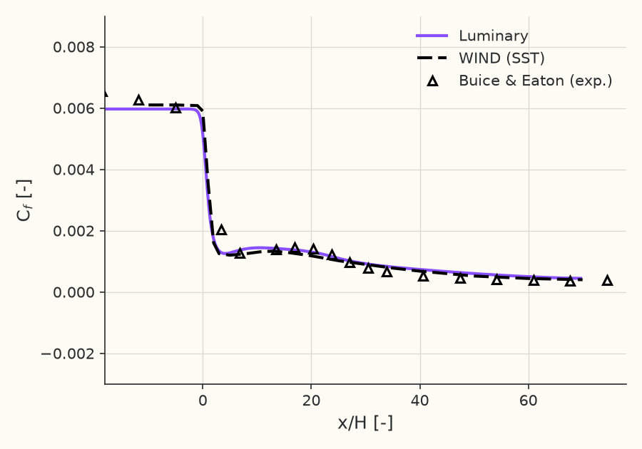
Reference: T. DalBello, V. Dippold III, and N. J. Georgiadis, "Computational Study of Separating Flow in a Planar Subsonic Diffuser," NASA/TM-2005-213894, 2005. (WIND (SST) upper-wall (fig. 8c)): https://ntrs.nasa.gov/citations/20050237896
Skin-friction coefficient on the lower (inclined) wall
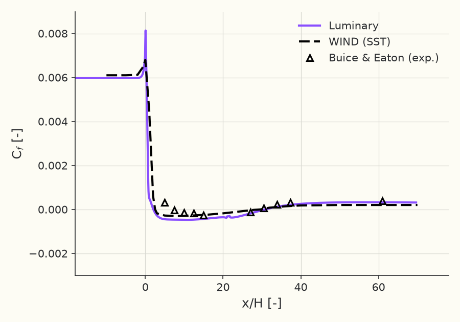
Reference: T. DalBello, V. Dippold III, and N. J. Georgiadis, "Computational Study of Separating Flow in a Planar Subsonic Diffuser," NASA/TM-2005-213894, 2005. (WIND (SST) lower-wall (fig. 8b)): https://ntrs.nasa.gov/citations/20050237896
Solver configuration
- features exercised
- VerificationValidation2DRANSk–ω SSTIdeal gasSteadyEnergy equation