2D Airfoil Near-Wake (Turbulent Wake)
verification
Overview
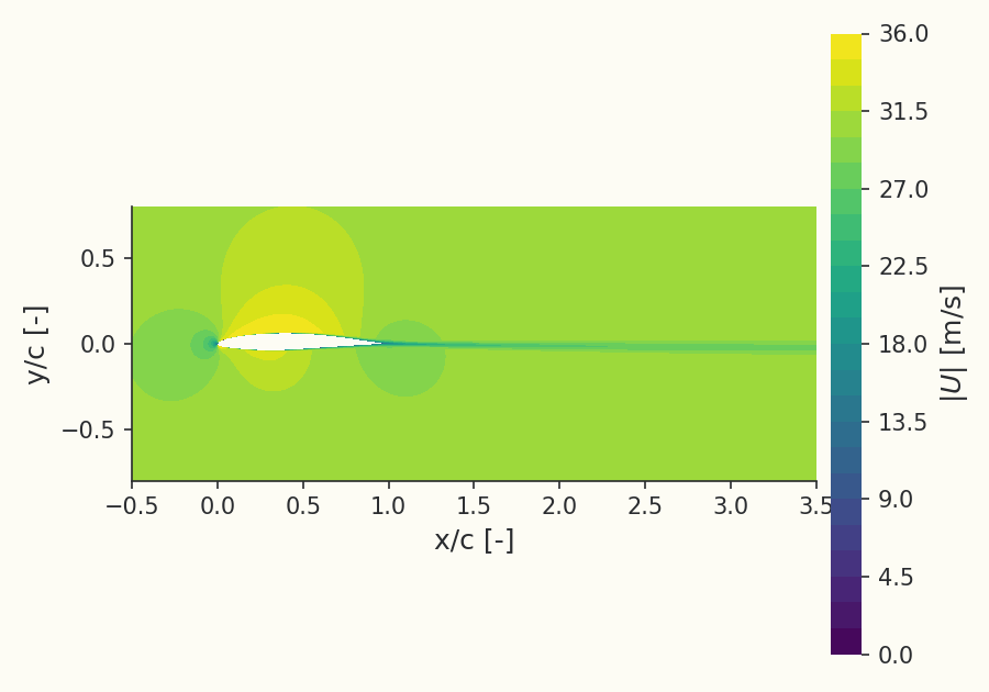
The 2D airfoil near-wake is a turbulence-model verification case focused on the turbulent wake that forms behind an airfoil trailing edge. As the boundary layers from the upper and lower surfaces leave the trailing edge they merge into a free shear layer with a streamwise velocity-deficit, which then recovers downstream. The quantities of interest are the depth of that deficit and its downstream recovery, away from any wall. The geometry is the Nakayama Model-A airfoil (with a sharpened trailing edge); with no analytic solution, verification here compares the solver's Spalart–Allmaras (SA) result, under grid refinement, against the NASA reference codes CFL3D and FUN3D.
The case runs at and (based on the airfoil chord) at zero angle of attack.
Problem Setup
The flow is compressible (ideal-gas air, Sutherland viscosity) at free-stream Mach number and chord Reynolds number , at . The computational domain extends to a farfield 500 chords away so that the boundary has no effect on the near-wake. Turbulence is modeled with Spalart–Allmaras, using the standard verification inflow value for the SA working variable.
Boundary conditions: a two-Riemann farfield on the outer boundary, an adiabatic no-slip wall on the airfoil, and symmetry on the two spanwise planes (the case is solved as a single-cell-thick quasi-2D slice). The grids are NASA's structured C-grid family, supplied as two point-matched zones (an outer region and a C-grid wrapped around the airfoil) and stitched here into one conformal mesh, used as published so the comparison to CFL3D and FUN3D is grid-for-grid.
Quantities of Interest
The primary verification quantity is the wake velocity-deficit: the streamwise velocity profile across the wake at stations behind the trailing edge (here and ), and the grid convergence of the minimum (deepest) wake velocity at , both compared to the CFL3D and FUN3D reference values. The integrated forces provide a second check: the lift coefficient , the total drag coefficient and its pressure () and viscous () components, and their convergence under grid refinement, plotted against the grid-spacing measure . On the finest grid (), Luminary gives (within 0.25% of the CFL3D value 0.16066 and 0.47% of the FUN3D value 0.15951) and (within 0.06% of the CFL3D and FUN3D value 0.010069). A finest-grid table reports the Luminary , , and numerically beside the two reference codes.
Sources
Reference force convergence (, , , ) and wake velocity-deficit profiles from the NASA CFL3D and FUN3D codes.
Results
Finest-grid and vs CFL3D / FUN3D
| Code | (total) | (pressure) | (viscous) | |
|---|---|---|---|---|
| Luminary | 0.16026 | 0.010063 | 0.0015301 | 0.0085331 |
| CFL3D | 0.16066 | 0.010069 | 0.0015339 | 0.0085356 |
| FUN3D | 0.15951 | 0.010069 | 0.0015312 | 0.0085381 |
Values on the finest grid (673×897 + 1025×449).
Reference: NASA Langley Turbulence Modeling Resource, "2D Airfoil Near-Wake Verification Case" (Nakayama Model-A airfoil, SA model).: https://tmbwg.github.io/turbmodels/airfoilwakeverif500c_sa.html
Grid convergence of total
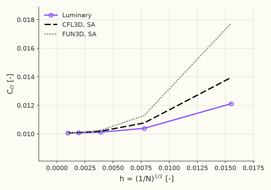
Reference: NASA Langley Turbulence Modeling Resource, "2D Airfoil Near-Wake Verification Case" (Nakayama Model-A airfoil, SA model). (CFL3D / FUN3D, grid convergence of the force coefficients): https://tmbwg.github.io/turbmodels/airfoilwakeverif500c_sa.html
Grid convergence of
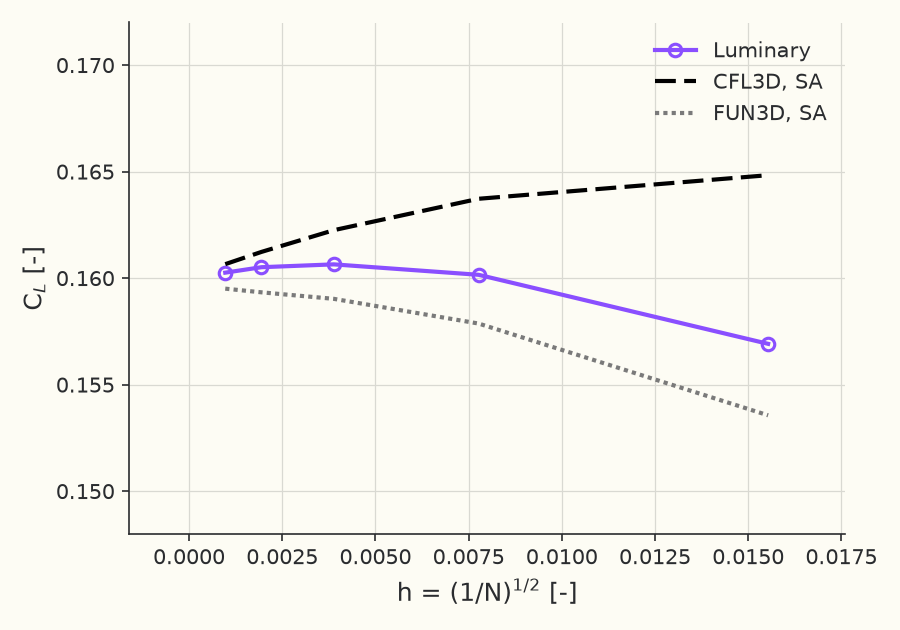
Reference: NASA Langley Turbulence Modeling Resource, "2D Airfoil Near-Wake Verification Case" (Nakayama Model-A airfoil, SA model). (CFL3D / FUN3D, grid convergence of the force coefficients): https://tmbwg.github.io/turbmodels/airfoilwakeverif500c_sa.html
Wake velocity profile at
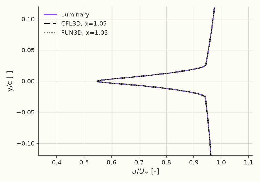
Reference: NASA Langley Turbulence Modeling Resource, "2D Airfoil Near-Wake Verification Case" (Nakayama Model-A airfoil, SA model). (CFL3D / FUN3D, wake velocity profiles (finest grid)): https://tmbwg.github.io/turbmodels/airfoilwakeverif500c_sa.html
Wake velocity profile at
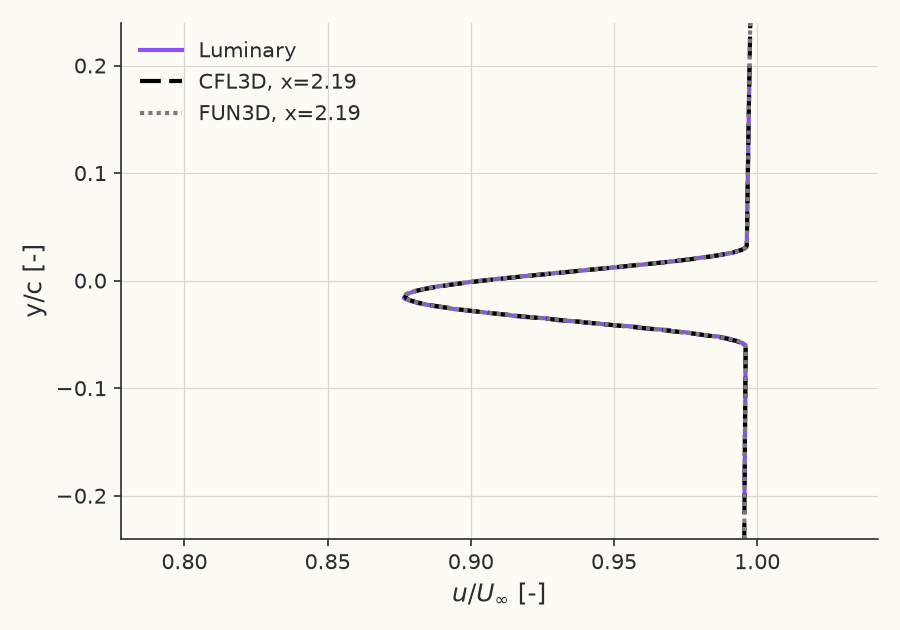
Reference: NASA Langley Turbulence Modeling Resource, "2D Airfoil Near-Wake Verification Case" (Nakayama Model-A airfoil, SA model). (CFL3D / FUN3D, wake velocity profiles (finest grid)): https://tmbwg.github.io/turbmodels/airfoilwakeverif500c_sa.html
Grid convergence of minimum wake velocity at
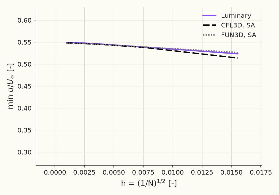
Reference: NASA Langley Turbulence Modeling Resource, "2D Airfoil Near-Wake Verification Case" (Nakayama Model-A airfoil, SA model). (CFL3D / FUN3D, grid convergence of the minimum wake velocity): https://tmbwg.github.io/turbmodels/airfoilwakeverif500c_sa.html
Solver configuration
- features exercised
- Verification2DRANSSpalart–AllmarasIdeal gasSteadyEnergy equation